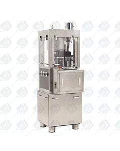
RTP10i Tooling Change
Welcome to LFA’s video on changing your RTP 10i tooling, knowing how to remove and change the tooling in your RTP10i is extremely important. It has to be done during a tooling change, cleaning and other repairs.
We’ll split this into 3 sections, removing tooling, replacing tooling and force feeder calibration. Each will be time-coded in the description below.
When working on your machine, always ensure there’s no power going to it.
Remove Tooling
First, stop the flow of formulation to the force feeder by adjusting the flow adjuster on the hopper. Turn this clockwise all the way in and this will stop the flow.
You can now lift the hopper out of the top of the machine. Once done open the perspex shield and remove the hopper extender, this will still contain formulation.
Using a 17mm spanner, undo the 2 bolts that attach the force feeder to the force feeder plate.
Now lift up the force feeder sheath with one hand and slide the force feeder towards you.
Remove the upper tracking housing by removing the 7 screws with a cross-head screwdriver, there are 3 at each side and one at the top. Once these are removed, the housing will slide out.
Now rotate the turret by hand so none of the top punches is on top of the turret key. Take a 5mm Allen key and remove the bolt.
Now rotate the turret again so a punch is on top of the key. You can now remove both the turret key and the punch at the same time. The reason for this is because the key is too wide so it can’t be removed without a punch coming with it.
Again rotate the turret by hand and start to remove the upper punches through the keyed section, one by one until all of the upper punches are removed.
We’re now going to remove the dust extractor unit which is located at the rear of the machine and is secured by 2 bolts which can be removed with a 5mm Allen key.
Remove the force feeder plate to give us more access to the lower turret shroud. Using a 6mm Allen key, remove the 3 bolts on top of the plate. You can then remove the plate.
Remove only this adjuster to give us access to the bolt below it holding the lower turret shroud. Turn anti-clockwise to remove it.
Using a 5mm Allen key remove the 4 bolts around the turret shroud.
Once the turret shroud is removed, we can start to remove the lower tooling. First access the inside the machine through the side panel. Push the puck inside up and out the top, ensuring the lower punch doesn’t fall.
Rotate the turret by hand and gently lower each lower punch out of the hole being careful not to damage the punches.
Next, we’re removing the dies, first, you have to remove the die locking nut from each station. If this is still in place, the die won’t move. Using a 6mm Allen key, remove the die locking nut.
Now take your drive bar which came with your RTP10i, enter it through the bottom of the machine where the lower tooling comes out and tap the die out of the die pocket. Then repeat this step with every station.
Replace Tooling
Now we can start to re-insert our new tooling. We’re going to be using LFA’s Die Seat Cleaner and Insertion Ring in the process. The RTP10i uses Euro D tooling, whilst the RTP 17i uses Euro B tooling.
To first clean the die seat of any formulation and debris, take your die seat cleaner and place it into the die pocket, now without applying pressure onto the top, hold the die seat cleaner by the sides and rotate clockwise for 2-3 turns.
Before placing your die into the pocket, we suggest using some food-grade assembly grease around the edge of your die ensuring it doesn’t go on to the die face, this will assist in replacing or removing later. Now place your die into the insertion ring.
Place the insertion ring with the die in, over the die pocket whilst placing a small amount of pressure on the die until you can feel it entering the die pocket. Now take your drive bar and entering through the upper punch guide hole and tap down on your die. When the die reaches the die seat you’ll hear a pitch change, this signifies your die is now in position.
Now use your insertion ring and run it over the top of the turret table and die, this will ensure its flush.
Re-insert the die locking nut and tighten, using a torque wrench the die locking nut should be tightened to 14 pound-foot. Repeat this for all of your dies.
Now we can start to replace the lower punches, before doing so we suggest lubricating the barrels of your punches with a barrel lubricant and using food safe assembly grease on the heads of your punches, see our tooling lubrication video for more information. Your enter the lower punches through the bottom of the machine up through the guide holes being extremely careful with the tips of the punches. You may feel some slight resistance as they enter but this is normal.
Now rotate the handwheel so the punch isn’t over the hole, lower it so it’s flat on the surface. Now repeat this process for all of the lower punches. Always make sure that you are using the correct punches, using an upper punch in a lower punch position will damage your machine and tooling.
Replace the puck, guide it in with your hand ensuring that it’s straight and run your fingers over it after to ensure its flush. After pull the tooling down flat on the surface.
Replace the turret shroud and tighten the four 5mm bolts with an Allen key.
Replace the Dust Extraction unit, tightening the two 5mm bolts.
Replace the force feeder adjuster, when replacing ensure you have the non-threaded side facing upwards.
Place in the force feeder plate and replace the 3 bolts with a 6mm Allen key and turn them only a couple of times to allow us to make adjustments. They’re 3 adjusters under the plate, each one adjusts a different side of the plate. We’re aiming to have the plate flush with the die table.
To do this we’re using a straight edge, place on the force feeder plate and the die table, make the adjustments in small increments and look for the gap between the straight edge and the die table, move the straight edge along the die table to make sure there’s no gap down the full length.
Once your happy with the calibration, tighten the bolts finger tight as we will still have to make some final adjustments to the force feeder unit.
We can now start to replace the upper punches, as before we suggest lubricating the barrel of the punches with a barrel lubricant and the heads of the punches with some food-grade grease.
Insert the upper punches through the keyed section of the upper tracking, rotate the turret with the handwheel. When doing this it’s extremely important that the heads of the punches remain above the tracking, if the machine is run with the heads under the tracking it will damage both your machine and tooling.
On your final upper punch, the tracking key needs to be replaced at the same time as the final punch. Once replaced rotate the turret with the handwheel and replace the locking bolt for the key, ensure this is well tensioned.
Then replace the upper tracking housing with the 7 screws.
Force Feeder Calibration
Next, we’re going to replace the force feeder but before we do, remove both the scraper blade and the tablet take-off blade with a crosshead screwdriver as these need to be replaced with the force feeder in position.
Replace the force feeder on the plate, when placing the force feeder make sure this bottom shaft is facing forwards so the sheath can easily pass over it. Reinsert the bolts and tighten fully. Using an adjustable wrench we can now make final adjustments with the force feeder on.
Using feeler gauges you can measure your force feeder calibration. We recommend starting at 0.15mm, it will feel tight but the feeler gauge should still be able to pass under. If you still find too much formulation on your turret table when running the machine, then you may choose to reduce that further. However, reducing this will wear out the brass wear part on your force feeder quicker and reducing too much may potentially damage the die table so it’s suggested to start off higher.
Once happy with the calibration, replace the scraper blade. This is a wear part that will wear over time. Firmly push down on the scraper blade and tighten with a crosshead screwdriver, this part needs to be tight against the die table to stop the excess powder from escaping.
Replace the tablet take-off blade, this doesn’t need to be pushed down to the die table. Instead it needs to be mounted one-third of the tablet height. For example, if you have a 3mm tablet height, the blade needs to be 1mm high, it’s not exact but approximately. It needs to be high enough for the excess powder to pass under but not a compressed tablet.
Once the force feeder is set up, remove it and fully tighten the three 6mm bolts under it with an Allen key and then replace the force feeder and the two 17mm bolts and tighten fully.
Finishing up
We can now replace our hopper extender through the side of the machine and our hopper through the top of the machine.
Adjust the flow adjuster on the hopper to release the formulation down into the force feeder.
Now test the machine without formulation, always do this by hand first using the handwheel and listen for any abnormal noises or any resistance whilst rotating.


